Describe the Necessary Setup Procedures to Use Timer Interrupt
Go To The Clock Configuration. For an interrupt to occur these five conditions must be simultaneously true but can occur in any order.

Timers
Pins are called T0 Timer 0 input and T1 Timer 1 input these two pins belong to port 3 Timer 0 when CT 1 pin P34 provides the clock pulse and the counter counts up for each clock pulse coming from that pin Timer 1 when CT 1 each clock pulse coming in from pin P35 makes the counter count up.

. To calculate the timer frequency for example 2Hz using Timer1 you will need. An interrupt occurs when the IO request completes. Therefore their executions are not blocked by bad-behaving functions or tasks.
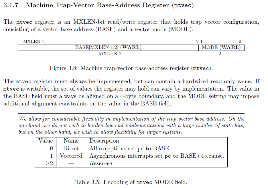
This important feature is absolutely necessary for mission-critical tasks. Set TMR0ON to 1 to turn on the timer. The 0x0 address is the reset interrupt vector.
And the timer module will be clocked at the internal clock frequency. Set The System Clock To Be 72MHz Or Whatever You Want. CPU frequency 16Mhz for Arduino 2.
You will need to know the circumference of the wheel. Void InitTimer0void TMOD. Each of the timers has a counter that is incremented on each tick of the timers clock.
This is done by adding a time register whenever the supervisor gives control to a program. You simply have to connect the LCD to the PIC as we did in interfacing LCD tutorial. BOOL terminate false.
This is necessary because the interrupt vectors which we will use in this lab are located in the low addresses of program memory 0x000xFD. Set The RCC External Clock Source. Before incrementing the value of the timer is compared to OCR.
5 hardware event trigger. The idea of this application is so easy and clear. Set T0CS to select clock source.
Enable timer interrupt. Control is then sent back to the supervisor. Name Generate The Project Initialization Code For CubeIDE or The IDE Youre Using.
Maximum timer counter value 256 for 8bit 65536 for 16bit timer 3. Set CS10 and CS12 bits to configure pre-scalar of 1024 Enable timer1 overflow interrupt TOIE1 the register is shown below Enable global interrupts by setting global interrupt enable bit in SREG Toggle the LED in the ISR and reload the TCNT value. Preload timer 65536 - 8000000 1024 50 TCNT1 65380.
Load the TCNT1 register with the value calculated above. The OS responds by queuing to the process. In our case i n PIC16F877A the 33 rd pin RBOINT is.
Program call a function which is typed by me for each timer interruptsAnd these interrupts will be programmed with setvect and getvect functions. Precise interrupt time is more precise than the interrupt time that QueryInterruptTime reports because the functions that report precise interrupt time read the timer hardware directly. Its easy to setup Timer 2 to interrupt once per millisecond Prescale 116 Postscale 110 PR2 75 -1 and then count off 1000 interrupts.
Timer interrupt goes off. Set bit 0-3 to select appropriate prescaler. In this lab well set up the timer to generate interrupts and thenEnable and configure the Timerwrite the code that responds to the interrupt.
Timers interval is very long ulong millisecs. Now to connect the interrupt pin we should look at the datasheet to know which pin of the PIC is used for External interrupt. Reset timer reset_timerMTIME_CLK_FREQ 2 BLINK_FREQ.
And theres no way to divide by a fractional amount. Make sure your interrupt service routine is working. LED pin void setup pinMode LED OUTPUT.
We use a timer interrupt. Pin P20 is named as Out Function declarations void cct_initvoid. Divide CPU frequency through the chosen pre-scaler 16000000 256 62500 4.
CTC timer interrupts are triggered when the counter reaches a specified value stored in the compare match register. Set entire TCCR1A register to 0 enable Timer1 overflow interrupt. Consider the reed switch to be a normally-open button and connect as usual with a 10k ohm pull-down resistor.
Set entire TCCR1A register to 0 TCCR1B 0. Set 1024 prescaler bitSet TCCR1B CS12. 4Process is executing again.
A sequence like this can occur. Make all ports zero InitTimer0. We will set it to zero since we want the timer to increment from internal clock.
7f secondsn doubleInterruptTime double10000000. Describe the sequence of steps that occurs on an HCS12 to initiate execution of the ISR once a valid IRQ on port J pin 7 is signaled 7 points. Which turns out to be more valuable than our own time.
And to be able to stop the thread do not use sleep but use WaitForSingleMultipleObject s with a thread termination event. Those can be delivered to the process as part of the timer interrupt. Disable global interrupts TCCR1A 0.
At this point the timer0 is up and running. Describe the sequence of steps that allows the HCS12 to return from the ISR to the main program with global interrupts enabled. Set up interrupt by configuring mtvec register_trap_handlerhandle_trap.
Divide result through the desired frequency 62500 2Hz 31250 5. For example a reed switch and magnet. But its overflow is not causing an interrupt.
Trying to work with Timer 0 rollovers will never give you exactly one second because Fosc4 216 12MHz 65536 1831055. An interrupt causes the following sequence of five events. If the two are equal a COMPARE MATCH interrupt is generated.
Initialize Timer1 cli. You therefore- also still need an appropriate jmp or rjmp instruction at 0x0. A compare match interrupt is called when the value of the timer equals a specific value set by the user.
Process queues asynchronous IO request. Start Timer0 while1 Rest is done in Timer0 interrupt void cct_initvoid P0 0x00. However it turns out to be impossible to implement using Delays without sacrificing the time of the CPU.
Hardware you will need a sensor. It now supports 16 ISR-based timers while consuming only 1 Hardware Timer. Enable The Timer Interrupt Signal In NVIC Tab.
1 device arm 2 NVIC enable 3 global enable 4 interrupt priority level must be higher than current level executing and. Interrupts and the GP Timer. Process is executing again.
The most important feature is they are ISR-based timers. The circuit diagram for using PIC16F877 interrupts is given in the above image. Set T08BIT to select between 8 and 16 bit operation.
Int mainvoid cct_init. Steps to configure the Timer Interrupt. This value is set by setting the value of OCR register.
Well also experiment with generating an exception by attempting to configure a peripheral before its been enabled. This is simply another area in which Delay-Based systems remarkably fail compared to Timer-Based ones. All you need is to start a parallel thread which does your periodik work in a cicle and once the work is done - it sleeps for 5 minutes.
The machine timer interrupt is exception code 7 as shown in so we put the timer_handler function at index 7 of the array. Int LED 1. Prescalers and the Compare Match Register.
The register decrements each time the clock ticks and when the timer reaches zero the timer interrupt bit is set to 1 which means that a time interrupt has occurred. For example It would be very nice if I have a c code which prints Hello worldn to screen once in a second without any sleep or delay functionI mean the code that print hello world must be in a function and for each. Assume an interrupt occurs on Port J pin 7.
Include Out Pin sbit Out P20. The Uno has three timers called timer0 timer1 and timer2.
Timer Interrupt An Overview Sciencedirect Topics

Timer Interrupt An Overview Sciencedirect Topics

Avr Microcontroller Leds Flasher Using Timer Timers Interrupts Timer Ctc Mode 6 Steps Instructables

Timers 8051 Timer Programming

Timer Interrupt An Overview Sciencedirect Topics

Timer Interrupt An Overview Sciencedirect Topics

Interrupt Service Routine An Overview Sciencedirect Topics
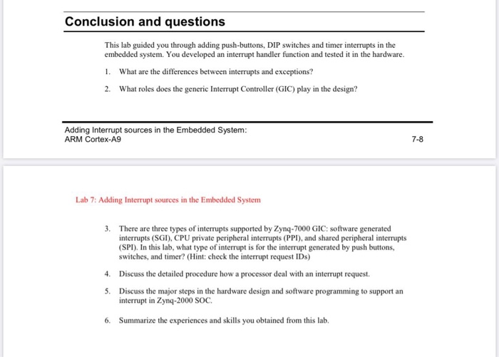
Conclusion And Questions This Lab Guided You Through Chegg Com

Timers
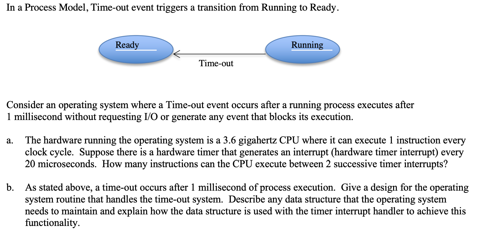
In A Process Model Time Out Event Triggers A Chegg Com
Chapter 12 Interrupts
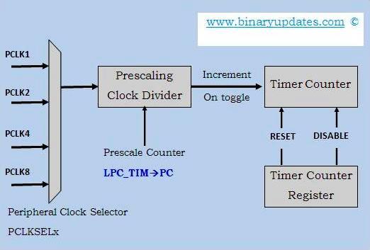
Timer Interrupt In Lpc1768 Microcontroller

Avr Microcontroller Leds Flasher Using Timer Timers Interrupts Timer Ctc Mode 6 Steps Instructables
Handling Interrupts And Traps Riscv Os In Rust

Chapter 12 Interrupts

Timer Interrupt An Overview Sciencedirect Topics
Chapter 12 Interrupts

Interrupt Handler An Overview Sciencedirect Topics
Chapter 12 Interrupts


Comments
Post a Comment